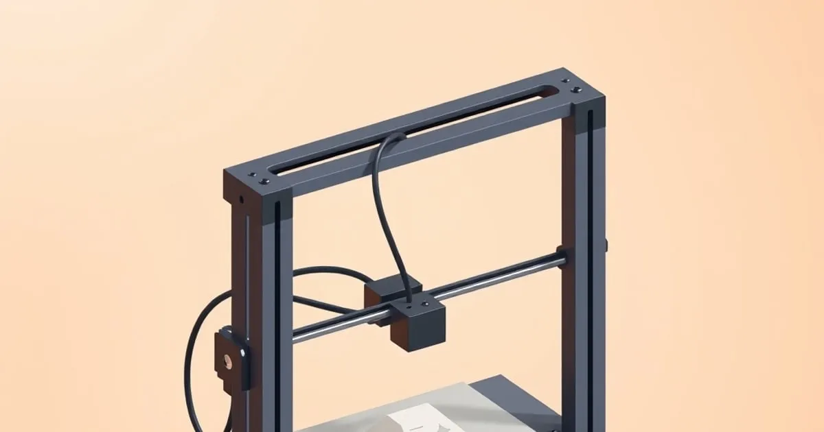
Knowing how to level a 3d printer bed manually is the single highest-value calibration skill you can develop. Auto-leveling probes — BLTouch, CR Touch, Klicky, the built-in routines on Bambu printers — measure the bed surface and apply compensation, but none of them replace a mechanically flat starting point. Adhesion problems that survive a good level are a separate diagnosis; see bed adhesion troubleshooting. If your four corners are 0.5 mm out of plane, the mesh has to stretch that correction across every layer, which causes uneven extrusion and missed adhesion at the extremes. Get the mechanical level close first; let the mesh handle the residual.
This covers the full process: prep, the paper drag method, corner order, how many passes you actually need, and how to read a first-layer test to know whether you are done.
Before you start: tools and printer state
Tools you need:
- One sheet of standard 80 g/m² office paper. Nominal thickness is approximately 0.10 mm. This is your feeler gauge — nothing more exotic is required.
- Isopropyl alcohol at 90% or higher, and a lint-free cloth.
- Access to the printer’s LCD or a slicer with manual control (to home and disable steppers).
Printer state before touching anything:
Bring the nozzle and bed to full printing temperature before leveling. The bed, the frame and the spring steel sheet all grow as they warm, and a sheet sits slightly differently hot than cold, so a gap set cold is not the gap you print at. For scale, aluminum expands roughly 23 µm per °C per meter, which is about 216 µm of in-plane growth across a 235 mm plate taken from room temperature to 60 °C; that figure is lateral, and it is the frame and the sheet seating, not the plate widening, that moves the nozzle-to-bed gap. Level cold and you are off by design.
For PLA: nozzle 200–215 °C, bed 55–65 °C. For PETG: nozzle 230–240 °C, bed 70–85 °C. For ABS: nozzle 240–250 °C, bed 100–110 °C.
Wipe the build surface with IPA immediately before leveling. Finger oils are enough to create adhesion failure on PEI or glass, and any debris under the sheet will give you a false high spot you will chase for an hour before finding it.
The paper method: step by step
Step 1 — Home all axes, then disable steppers.
From the printer LCD or slicer manual control, run a full home (G28 on Marlin-based machines). Then disable the steppers via M84 or the LCD equivalent so you can slide the printhead by hand. Leave the bed and nozzle hot throughout.
Step 2 — Set all corner knobs to mid-range.
Tighten every corner adjustment knob until it bottoms out, then back each off three full turns. This puts all four corners at equal starting height and gives you adjustment range in both directions. Running a knob fully out during leveling is a sign you started too low; fully in means too high. Mid-range prevents both.
Step 3 — Position the nozzle over the front-left knob.
Slide the printhead so the nozzle sits directly above the adjustment knob — not the corner of the bed, but the spring/knob location. Place the paper under the nozzle.
Step 4 — Adjust until you feel slight drag.
Loosen the knob to raise that corner toward the nozzle (the spring pushes the bed up) and tighten it to lower the corner, until the paper slides with noticeable resistance when you pull it. Which way is “tighten” depends on whether you view the knob from above or below, so watch which way the corner moves. It should not be clamped: if you cannot pull it at all, lower that corner. It should not be free: if it slides with zero friction, raise the bed. The MatterHackers bed leveling guide describes the target as “a very slight resistance when you pull on the paper,” with consistent pressure across all four points defining a level bed.
Step 5 — Work corners in a star pattern, not a circle.
The corners interact: adjusting front-left shifts rear-right slightly. Going around the bed clockwise amplifies this interference. Use a cross pattern instead:
- Front-left
- Rear-right
- Front-right
- Rear-left
Then return to front-left and recheck. That completes one pass.
Step 6 — Do three passes minimum.
Pass one sets a rough plane. Pass two makes smaller corrections. By pass three you should be at quarter-turn tweaks or less. If you still see large corrections on pass three, suspect a warped build surface or a damaged spring under one corner.
Step 7 — Check the center.
Slide the nozzle to the center of the bed and test with paper. The center is not adjustable with corner knobs. If it reads high, the bed is bowing upward; if low, it is concave. A bow under 0.10–0.15 mm is manageable with mesh bed leveling. More than that, the surface needs replacing or the printer needs a multi-point auto-level system to compensate adequately.
Reading the first-layer test
After mechanical leveling, print a single-layer calibration square or a first-layer test grid across the full build area. Read the lines:
- Too far: lines are round on top, do not bond to each other, curl away from the surface. Lower Z-offset by 0.05 mm increments, or raise the bed slightly.
- Too close: lines are crushed flat, merge into a fused sheet, leave ridges at their edges, or clog the nozzle on the second pass. Raise Z-offset, or lower the bed.
- Correct: lines are slightly flattened with a smooth top surface, just barely touching their neighbors at the edges, firmly bonded to the build plate. No gaps, no ridges.
For the final 0.05–0.10 mm of tuning, use software Z-offset correction rather than touching the knobs. That step is the heart of our first layer calibration guide. Prusa’s bed level correction documentation recommends adjustments in 10-micron increments for per-corner software correction — even 20 µm changes are visible in the first layer at 0.20 mm layer height. The same incremental logic applies to the Live Z or baby-stepping function on any Marlin-based printer.
When to re-level
Manual leveling drifts. Check it when:
- You swap the nozzle or hotend. Mount height changes even if the nozzle brand and size match.
- You swap build surfaces. Smooth PEI, textured PEI, glass, and spring steel sheets have different thicknesses; swapping one for another shifts your effective Z-offset.
- After a crash or layer shift. The printhead impacting a failed print can shift the X gantry or loosen a bed spring.
- After transport. Moving the printer disturbs spring tension and frame alignment.
- Seasonally on open-frame printers. Ambient temperature changes shift the frame geometry on machines like the Ender 3 series or Artillery Sidewinder. Enclosed printers (Bambu P1S, Prusa MK4 in its enclosure) are more stable but not immune.
On a typical open-frame printer running PLA, plan a leveling check every 10–15 print hours or once a week for daily use.
What auto-leveling does and does not fix
Probe-based systems (BLTouch, CR Touch, Klicky, eddy-current sensors on the Bambu X1C) generate a mesh map of the bed surface. The firmware then compensates the Z position at each mesh point during printing. This is effective for surface topology — small local high and low spots from warping or scratches.
What it does not fix: a mechanically out-of-level bed. If the left side of the bed is 0.8 mm lower than the right, the probe sees that and applies compensation, but the correction value stretches thin across the mesh interval and the actual first-layer height still varies. Manual leveling first, mesh compensation second is the correct order — not one or the other. Re-check it on the schedule in our printer maintenance routine. Tom’s Hardware’s bed leveling walkthrough makes the same distinction: the goal of manual leveling is to get the bed flat enough that auto-level has a small residual to handle, not a large offset to paper over.
After mechanical leveling, return to the first layer calibration order for the mesh, nozzle-height and extrusion checks.
Related across the network
- Anycubic Bed Leveling: The Paper Method and Z Offset — anycubicguide.com
- Creality Bed Leveling, First Layers, and Extrusion Tuning — crealityreviews.com


